Identification MF and Fragment Offset
For Complete YouTube Video: Click Here
We will try to understand Identification MF and Fragment Offset in this class.
We have already explained the concepts of Segmentation, Fragmentation, and Reassembly in our previous class.
Identification MF and Fragment Offset
The Identification MF and Fragment Offset are the fields in the second row of the IPv4.
To understand this concept, we will consider the image below.

Consider that source A has 1000 Bytes of data to be transferred to destination B.
The 1000 Bytes of data in the application layer will be transferred to the transport layer below.
The transport layer will add the transport header of 20 Bytes to the data.
The transport layer will do the segmentation by identifying the bottleneck in the below layers.
From the above network, it is evident that the network has a maximum capacity of 500 Bytes.
The data segment of 1020 has to be divided into 480 bytes each, to which the network layer will add the network header.
The image below shows how the transport layer does the segmentation.

We will try to understand the values given for Identification MF and Fragment Offset fields in each packet.
The identification number is to identify that all packets belong to the same packet but are fragmented.
For example, assume that the identification number is 80, so all the fragments will have the same identification number, 80.
The MF stands for More Fragments.
If a packet has more fragments, the MF field is set to 1. If no fragments are following, the MF is set to 0.
How is the fragment offset provided?
The fragment offset is the number of data bits ahead of the fragment.
If we consider our fragments, the number of data bits ahead for the first fragment is zero, so the fragment offset is zero.
Similarly, the fragment offset of the second packet is 480 because the number of data bits before it is 480.
The fragment offset for the last fragment is 960.
The image below shows the Identification MF and Fragment Offset for each packet in the transmission.

Now the packets are forwarded to the data link layer, and the data link layer frame will get added and transmitted as shown below.

All the data frames will get received at the destination.
The router must transfer the data to an interface to reach the destination.
The underlying network has an MTU of 300 bytes only.
The router will now fragment the packets to fit the MTU of 300 bytes.
Each packet will get fragmented to 280 bytes.
To that, the network header is added.
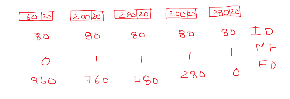
Now the Identification MF and Fragment Offset are added to each packet.
The identification number is 80 for all the packets.
The MF is set to 1 for all its fragments if the parent packet has an MF of 1.
The MF is set to 0 for the last fragment if the parent packet has an MF of 0.
The fragment offset uses the same principle as discussed above and will set all the fragment offsets as shown below.

